 Laird Connectivity is now Ezurio
All about Ultra-Wideband #3: The Importance of Topology
In our last post we discussed the ultra-brief pulses that make UWB’s RF behavior unique. In this post, we’ll look at the UWB protocol itself, and the relationship between throughput and power usage.
Published on January 16, 2024
Understanding Data Rates and Network Topology in UWB
We previously discussed ultra-wideband’s particular RF behaviors and how its ultra-brief pulses create a signal that is both fundamentally low-power and also fundamentally good for propagation without interfering with other technologies. The characteristics of those brief pulses create the wide frequency bandwidth that makes UWB unique, and also decrease latency in the link. That has the potential to create high data rates, but that’s not the entirety of the story. As with any wireless standard, the specific implementation of a protocol is ultimately what determines how well it performs, how much throughput can be achieved, and what the ultimate level of speed and performance will be for the wireless link.
These positioning topologies arise out of the fact that UWB radios can be of either the tag or anchor type, and tags can serve in the role of anchors (with some limitations) in a location sensing application. Those limitations arise out of the modes available to tags and anchors for operation, which are different and vary by chipset.
The level of location accuracy in UWB is the result of several factors including the topology you use and the power consumption your devices can afford. In this post we’ll look at two modes of communication with UWB: Time Difference of Arrival (TDoA) and two-way tag ranging. The differences between their capabilities in terms data rates arise from the capabilities inherent to anchors vs. those inherent to tags, and while they are both useful modes of location sensing, they differ in some significant ways.
Understanding Tags-as-Anchors, Two-Way Ranging, and Time of Flight
To start, it’s important to recognize that there are
differences between UWB tags and anchors on a hardware level. Anchors are
specifically designed with multiple antennas and to be set up in fixed
locations, and to leverage a higher power consumption to free up tags to use
less power. Tag chipsets and anchor chipsets tend to be completely different,
but they are both able to achieve similar effects, with a few tradeoffs.
First, let’s look at two-way tag ranging. To start
with: tags are capable of determining range to other tags, and even 2D and 3D
positioning when tags are used in fixed locations (similar to anchors). Full 3D positioning is possible when
3 tags are used as anchors in a fixed position. Because tags are a
single-antenna solution, they lack the ability to measure an incoming signal’s
trajectory (on the x, y, and z axis) like an anchor with multiple antennas does.
Multiple tags are needed to gather this full picture, but because they are tags
and not true anchors, they are required to communicate bidirectionally (hence, two-way
ranging) to accomplish this. Each tag-as-anchor must have a bidirectional
channel open with each tag, which occupies the tag much more heavily than the
TDoA alternative where tags only transmit. This is accomplished by calculating Time
of Flight.
The advantage here? There’s quite a bit you can do at a lower
cost in terms of hardware, including use cases where less frequent location
updates are needed. All the way up to full 3D position is possible and with
simpler hardware than is required by an anchor-based setup. Importantly,
though: this bidirectional communication is costly in terms of throughput for
the client. The overall update rate is significantly reduced by the tag’s need
to maintain connection and calculate time of flight. With two-way ranging, more
power is needed for the necessary transmit/receive of UWB packets compared to the
“transmit-only” requirement when tags are used with anchors in TDoA mode.
Understanding Anchors, TDoA, and Angle of Arrival
By contrast, anchors are able to sense and calculate position of tags using their more complex hardware and free up resources on the tag to operate with lower power. As we discussed in our first post on ultra-wideband, this is accomplished with a combination of Time-Difference-of-Arrival and Angle of Arrival. In this mode, UWB tags don’t need to maintain bidirectional communication with an anchor. They only need to pulse very briefly to communicate their location. At the anchors, two important measurements are made and typically calculated by an attached backend engine receiving the data from the anchors.
The first important value is the time variance between when a pulse arrived at each anchor (if using more than one anchor) which is a Time Difference of Arrival calculation. This is enough to get useful information about the possible location of a tag, and with as few as 3 anchors, that position can be triangulated fairly accurately.
The second is the time variance inside each anchor of when a pulse arrives at each antenna of an anchor, lending insight into the heading of the tag relative to the anchor, an Angle of Arrival calculation. Typical anchors have three antennas, oriented across the x and y axes, will receive a pulse from a tag at slightly different timings based on the different position and orientation of each antenna, as well as the slightly different orientation of the tag to each antenna. This timing difference can be used to calculate azimuth and elevation angles in addition to the range from the tag to the anchor.
The critical thing here is that the tag has much less work to do in order to broadcast its position. A simple pulse is enough to give the anchors and positioning engine enough information to figure out its location, reducing the amount of communication and processing the tag must perform by itself. In so doing, this topology enables much higher throughput and location accuracy than is possible by using tags alone.
Also critical is understanding the much higher complexity in integrating true anchors in a system. Anchors must be precisely positioned, oriented, and tuned to yield accurate information about tag positioning. This integration effort must be extremely precise. Additionally, the cost of true anchors is much higher than the cost of a fixed tag implemented as an anchor.
Example Topologies
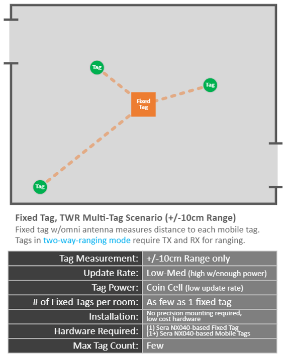
Let’s look at topologies beginning with the least expensive and least complex. For example, you can achieve simple ranging with a fixed tag (simulating an anchor). This will not provide location in full 3D space, but allows coin cell operation on the tags (with a lower update rate):
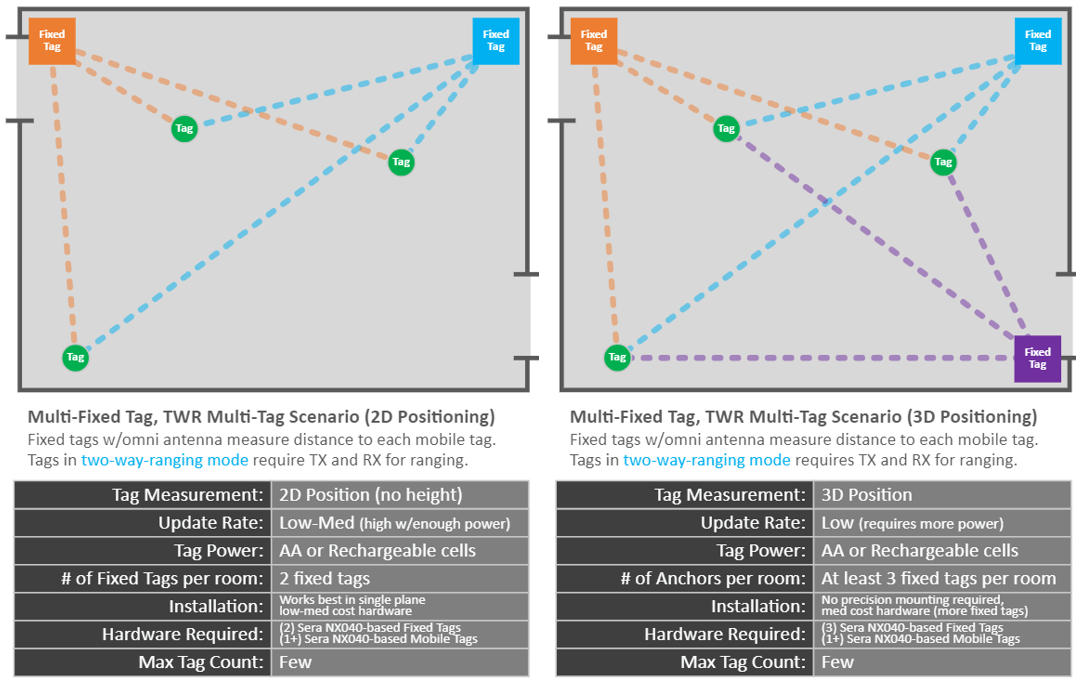
It’s also possible to use multiple fixed tags to get actual 2D position or 3D positioning a space, at the cost of more power. This is how our Sera NX040 demo achieves 3D positioning for multiple tags in a space, without using a single anchor (more on this in a future blog post):
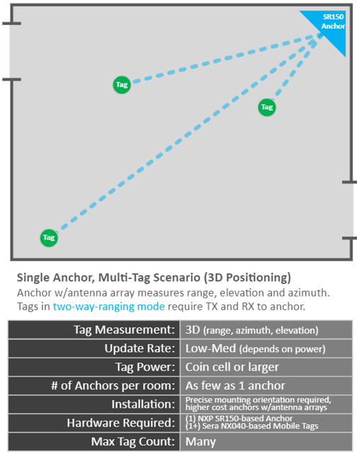
In the next example, using a single true anchor (e.g. based on the NXP SR150 chipset), it’s possible to get 3D positioning with only one reference point. However, even in this scenario, we are not utilizing the TDoA mode which lowers a tag’s power consumption to the absolute minimum by enabling “blink” mode. A single anchor still requires two-way ranging to ascertain the location of the tag, and therefore still requires more time over the air and more power consumption from individual tags in the system:
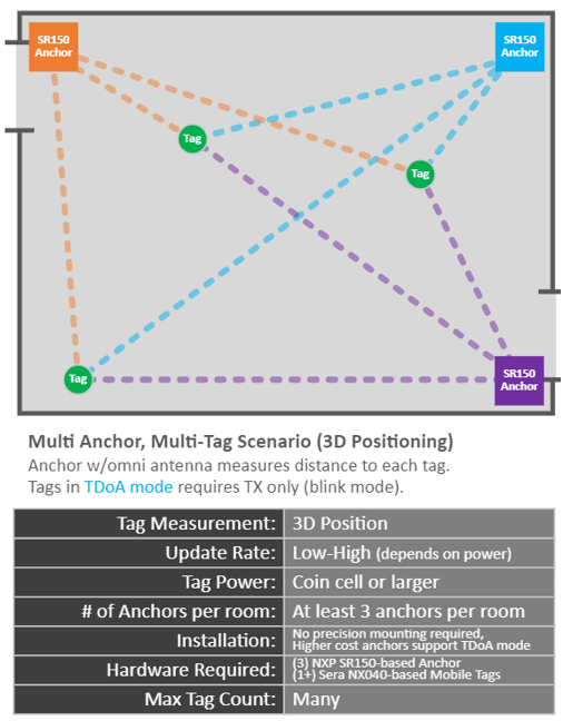
Finally, utilizing multiple fixed/dedicated anchors (as opposed to fixed tags operating as anchors) results in the lowest latency and tag power consumption by allowing tags to operate in blink mode. Blink mode means tags simply have to send a simple ping to be located by the anchor infrastructure, without performing any on-device calculation. It also allows many more tags to be collocated in the same space.
This implementation is the most costly, as well as the most difficult in terms of tuning, integration, mounting precision, and more.
There are many ways to implement a UWB positioning topology and each has their own capabilities, power characteristics, and tradeoffs. The important thing is to identify the level of precision and power needs that define your application and to design to those requirements.
The Takeaway: Design To Your Actual Requirements
As you can see, UWB provides multiple ways to calculate position through multiple schemes and topologies, and with differing results. In order to build the UWB positioning solution that works best for you, it’s important to consider those fundamental characteristics that are most required in your application.
- Is tag power consumption critical? Is high update rate critical? Tags that use the least power can be deployed into the field and last for long durations without so much as a battery change. This will come at the expense of a more complicated UWB infrastructure, because it requires true anchors (which are more expensive than tags).
- Do you need to track lots of devices, or just a few? The tag-as-anchor (two-way ranging) topology allows less total tags to be tracked at once (unless you drop your throughput), but if your application truly only needs a few tags communicating simultaneously, or simpler location sensing (such as range-only location), it may be very practical to implement a tag-only architecture. The cost is lower, and the location accuracy may be more than sufficient for your needs (but will require a larger battery on each tag or lower update rate to compensate).
- Is small tag size a requirement? An anchor-based TDoA setup allows tags to run on a much smaller power source (such as a coin cell), where a purely tag-based architecture will require a larger power source such as AA batteries. The limited tag activity inherent in TDoA makes it possible to design a much smaller UWB tag, which may be a requirement for some applications. It will also support a much larger total number of simultaneously tracked tags.
These trade-offs are important considerations in how you decide to implement UWB. There are useful applications for each, but to the point of this post: high throughput and location accuracy is possible in UWB, but comes at a cost. It’s necessary for OEMs to be aware of these trade-offs when designing a UWB positioning network in order to arrive at the perfect balance of throughput, power consumption, accuracy, form factor, and device count.
Up Next: Our Sera NX040 Tag-to-Tag Positioning Demo
As we’ve established, there’s lots of ways to achieve 3D positioning with UWB. Our Sera NX040 demo utilizes three tags-as-anchors tracking one or more tags in 3D space. As we’ve discussed, there are differences between all of these topologies, but our Sera NX040 demo is one way of achieving 3D location with minimal difficulties in integration and at a lower cost than a traditional 3-anchor setup as well.
In our next post, we’ll look at the NX040 demo as one way of rethinking how UWB can be used for location tracking, and how it differs in terms of tag power consumption, integration efforts and costs, hardware costs, and more. Follow our blog for the next part of our series at:
www.lairdconnect.com/resources/blog
About Our UWB Modules
Our lineup of innovative new UWB modules seamlessly integrates cutting edge UWB silicon from NXP, with the processing and Bluetooth Low Energy (LE) capabilities of Nordic Semiconductor’s nRF52 SoC. The combination of the two enables significant advancements in granularity of location that improves existing Bluetooth LE beaconing and RSSI-based ranging. They’re optimised for battery-powered implementations and integrate additional memory, crystals and components to simplify your overall BOM and drive down the cost of integration.
This comprehensive hardware approach is complimented by a range of added value software, Python scripting capabilities, and desktop and mobile tools. Whether your application is hosted or hostless, we have options to suit your application’s needs, as well as your engineering team’s capabilities. All of this is then backed by our industry leading technical support, design services, and test services to help you simply implement UWB in your next project.
Our innovative integration of the best wireless silicon from NXP and Nordic Semiconductor has produced the secure, flexible Sera NX040 range. The series features tightly integrated hardware and RF designs, all optimized for low power operation and reducing the need for external clocks, filters and components. Already using Bluetooth LE for basic beaconing or RSSI-based ranging? Now, easily advance to the next level with NFC and UWB for more granular locationing and positioning. This granularity yields much higher accuracy compared to RSSI-only proximity applications in industrial environments.
Learn more at:
https://www.lairdconnect.com/sera-nx040-series