 Laird Connectivity is now Ezurio
Lyra 24 Series Bluetooth 5.4 Solutions
Overview
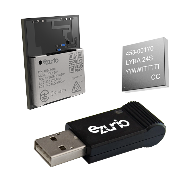
The latest addition to Ezurio's (formerly Laird Connectivity) extensive Bluetooth Low Energy (BLE) product range is the Lyra 24 Series, based on Silicon Labs EFR32BG24 SoC. This range of flexible modules, adapters and DVKs marries all the benefits of Silicon Labs hardware, software, and tools offerings with Ezurio's added value application software, services, certification, and support capabilities. This seamless partnership continues to provide customers with multiple software development options suited to their resources and skillsets in Bluetooth LE-enabled product development.
The Lyra 24 Series includes multiple small form factor PCB modules, as well as ultra-compact SIP options, to suit any host board footprint. These module options are accompanied by low cost, easy to use development kits and the addition of a certified, packaged USB Adapter to add Bluetooth LE connectivity to a plethora of additional products in your application set. Together, Silicon Labs and Ezurio, will drive down your total cost of ownership, design complexity and risk, whilst ensuring you the fastest time to market for your next Bluetooth LE-enabled IoT design.
- Bluetooth v5.4 Bluetooth Low Energy
- Widest range of MCU peripherals: UART, I2C, SPI, ADC, GPIO, PWM, Counter, Timer, Watchdog, PRS
-
Bluetooth Low Energy
- Support - Peripheral/Central Roles
- Support for 2 Mbps, 1Mbps, and 125 kbps coded
- Support for AoA / AoD, Bluetooth LE Mesh (C code path only)
- Based on Silicon Labs EFR32BG24 chipset
- Extended Industrial Temp Rating (-40° to +105 °C)
- Hostless & Hosted operation – Internal MCU reduces BOM
- AT Command Set
- C Development with Simplicity Studio
-
Powerful Core Cortex-M33
- 1,536 kB Flash
- 256 K RAM
- 1,536 kB Flash
- Fully featured development kits - Everything needed to start Bluetooth LE development
Build Your Wireless IoT Application with Canvas
Our Canvas™ software suite enables rapid embedded development across our MCU-based wireless products. Cross-chipset middleware, easy-to-use wireless APIs, on-module scripting and intuitive desktop/mobile tools are all available to dramatically ease embedded development.

See our Electronic Design Webinar with Silicon Labs
Future Proof Your Next Generation Bluetooth LE design – Capable, Flexible and Secure - The Lyra 24
Watch our webinar on the Lyra 24 family utilizing Silicon Labs EFR32BG24 SoC, designed to empower your next generation Bluetooth Low Energy (LE) projects.
Throughout the webinar, we provide practical insights, examples, and best practices for effectively leveraging Lyra 24 and its EFR32BG24 SoC in your Bluetooth LE products. Our expert speakers share their extensive knowledge, enabling you to make informed decisions while designing and implementing Bluetooth LE solutions. Additionally, we compare and contrast the capabilities of the current Lyra series (EFR32BG22) to the new Lyra 24, with an eye on end product markets and applications that would lend themselves to one or the other option.
Specifications
High-performance 32-bit ARM Cortex-M33® with DSP instruction and floating-point unit
256 kB RAM
| Part Number | Antenna Options | Antenna Type | Dimension (Height - mm) | Dimension (Length - mm) | Dimension (Width - mm) | GPIO | Other | Output Power | Packaging | Type |
|---|---|---|---|---|---|---|---|---|---|---|
 Recommended for New Design (RND) Buy Now | 10dBm Integrated antenna | Silicon Labs EFR32BG24 | 2.15 | 12.9 | 15.0 | Up to 26 GPIO with output state retention and asynchronous interrupts | Up to +10 dBm | Tape / Reel | Lyra 24P (PCB Module) | |
Recommended for New Design (RND) Buy Now | 10dBm Integrated antenna | Silicon Labs EFR32BG24 | 2.15 | 12.9 | 15.0 | Up to 26 GPIO with output state retention and asynchronous interrupts | Up to +10 dBm | Cut / Tape | Lyra 24P (PCB Module) | |
 Recommended for New Design (RND) Buy Now | 20dBm Integrated antenna | Silicon Labs EFR32BG24 | 2.15 | 12.9 | 15.0 | Up to 26 GPIO with output state retention and asynchronous interrupts | Up to +20 dBm | Tape / Reel | Lyra 24P (PCB Module) | |
Recommended for New Design (RND) Buy Now | 20dBm Integrated antenna | Silicon Labs EFR32BG24 | 2.15 | 12.9 | 15.0 | Up to 26 GPIO with output state retention and asynchronous interrupts | Up to +20 dBm | Cut / Tape | Lyra 24P (PCB Module) | |
 Recommended for New Design (RND) Buy Now | External antenna via RF trace pin | Silicon Labs EFR32BG24 | 2.15 | 12.9 | 15.0 | Up to 26 GPIO with output state retention and asynchronous interrupts | Up to +20 dBm | Tape / Reel | Lyra 24P (PCB Module) | |
Recommended for New Design (RND) Buy Now | External antenna via RF trace pin | Silicon Labs EFR32BG24 | 2.15 | 12.9 | 15.0 | Up to 26 GPIO with output state retention and asynchronous interrupts | Up to +20 dBm | Cut / Tape | Lyra 24P (PCB Module) | |
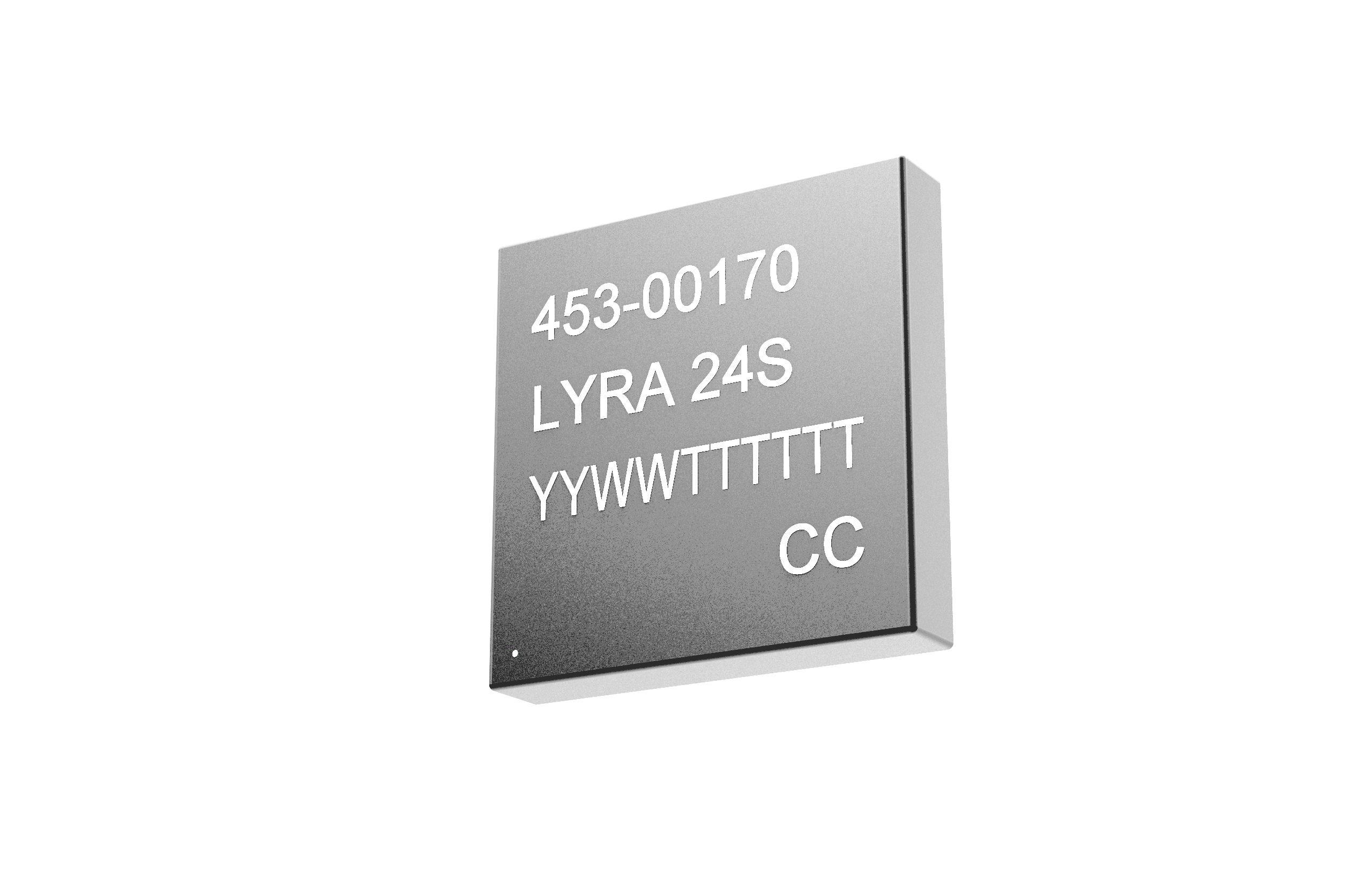 Recommended for New Design (RND) Buy Now | Integrated antenna OR external via RF trace pin | Silicon Labs EFR32BG24 | 1.18 | 7 | 7 | Up to 26 GPIO with output state retention and asynchronous interrupts | Up to +10 dBm | Tape / Reel | Lyra 24S (SIP Module) | |
Recommended for New Design (RND) Buy Now | Integrated antenna OR external via RF trace pin | Silicon Labs EFR32BG24 | 1.18 | 7 | 7 | Up to 26 GPIO with output state retention and asynchronous interrupts | Up to +10 dBm | Cut / Tape | Lyra 24S (SIP Module) | |
 Recommended for New Design (RND) Buy Now | Integrated antenna | Ready to add to any PC, laptop or any embedded device with a virtual COM port | Up to +20 dBm | Lyra 24P USB Adapter (PCB Module) |
Development Kits
-
/filters:background_color(white)/2024-03/453-00145-K1.png)
453-00142-K1
Lyra 24 Series - Development Kit - Bluetooth v5.4 PCB Module (10dBm) with integrated antenna
Antenna TypeSilicon Labs EFR32BG24 -
453-00145-K1
Lyra 24 Series - Development Kit - Bluetooth v5.4 PCB Module (20dBm) with integrated antenna
Antenna TypeSilicon Labs EFR32BG24 -
/filters:background_color(white)/2024-03/453-00148-K1.png)
453-00148-K1
Lyra 24 Series - Development Kit - Bluetooth v5.4 PCB Module (20dBm) with RF Trace Pad
Antenna TypeSilicon Labs EFR32BG24 -
/filters:background_color(white)/2024-03/Lyra%2024S%20SIP%20Dev%20Board.10.png)
453-00170-K1
Lyra 24 Series - Development Kit - Bluetooth v5.4 SIP Module with various antenna options
Antenna TypeSilicon Labs EFR32BG24
Documentation
I've connected my Lyra development board to my PC, but it does not show up in Simplicity Studio 5. What can I do?
Before contacting our support team, please follow the below mentioned steps for troubleshooting the connection between your Lyra development board and PC.
Hardware: Inspect the Lyra development board visually for any mechanical or physical damage. Try a different USB port on your PC and use the supplied micro USB cable. Also, verify that the SEGGER J-Link LED (in the bottom-right corner) is active when powered. If you own another DVK or got a spare board somewhere, then please connect it for validation and cross-checks to see if it works or not with the same setup.
Software: In Simplicity Studio 5, go to "Help" -> "Update Software" and apply all available updates if prompted. Check that both Simplicity Studio 5 installation and Silicon Labs Gecko SDK (GSDK) are up to date. Also, try to start Simplicity Studio 5 as an Administrator for testing reasons only. Make sure that your local firewall or antivirus program is not blocking any traffic / access. Install the latest version of the J-Link Software and Documentation Pack manually.
What is the Silicon Labs Proprietary Flex SDK and where can I find more information about it?
The Silicon Labs Proprietary Flex SDK is a complete software development suite for proprietary wireless applications. Per its namesake, Flex offers two software implementation options and paths:
- RAIL (Radio Abstraction Interface Layer) is an intuitive and easy customizable radio interface layer designed to support both proprietary and standards-based wireless protocols. It simplifies and accelerates the development process. This is the lowest layer available for all networking stacks in the Bluetooth Gecko SDK (GSDK).
- Connect is an IEEE 802.15.4-based networking stack designed for customizable broad-based proprietary wireless networking solutions that require low power consumption and operates in either the sub-GHz or 2.4 GHz frequency bands. This solution is targeted towards simple network topologies.
Do you support a Remote Command Mode (or something similar) in your AT Interface app like Wireless Xpress?
No. Unfortunately, we do not provide any support for a Remote Command Mode in our own AT Interface application at the moment which would e.g. allow AT commands to be sent, received, and processed over a BLE link (via GATT) – between two Lyra devices – for remote configuration reasons.
Yes. This feature is already on our Lyra (22) and 24 software roadmap. We’ve received many requests from different customers in the past asking us this question. The plan is to make it available in conjunction with both existing VSP (Virtual Serial Port) and non-VSP modes. See also our Lyra (22) and 24 Series – AT Interface Application User Guide for further details. We will provide more information on this topic once the implementation has been fully evaluated and finalized.
Is there a way in Simplicity Studio 5 to downgrade the Bluetooth Gecko SDK (GSDK) version?
Yes, it is possible. You can for example downgrade in Simplicity Studio 5 from the Bluetooth Gecko SDK (GSDK) version 4.4.0 to 4.2.1 at any time. Refer to https://www.silabs.com/developers/gecko-software-development-kit for the latest release notes documents.
First, launch Simplicity Studio 5 and go to the Welcome / Launcher page if necessary. Next make sure that you are logged in with your Silicon Labs account – otherwise please apply and register under https://www.silabs.com. Now open the "Install" window which by default can be located in the upper-left corner of the submenu.
Go to "SDKs" and search for "Gecko SDK - 32-bit and Wireless MCUs". Click on the three dots (...) right next to the current installed version number shown and select "Change Version". Confirm your choice and GSDK release by pressing the "Finish" button. This process may take a few minutes to complete.
Do you provide support for the RM126x and Lyra development boards through the Simplicity Studio 5 Software & IDE?
Yes, indeed we do. Similar like with other Silicon Labs based devices which you may have worked before already. Currently, all below mentioned RM126x and Lyra (22) + 24 development boards are automatically recognized and added to the “Debug Adapters” list once you connect them to your PC. They are displayed and found on the (Welcome) Launcher page within Simplicity Studio 5 – as usual. Simply speaking: This would be the starting point if you want to develop custom LoRaWAN / BLE applications in C when using our modules.
RM126x Series
- Ezurio RM1261 Development Kit (BRD2900A Rev A00),
- Ezurio RM1262 Development Kit (BRD2901A Rev A00).
Lyra 24 Series
- Ezurio Lyra 24P 10dBm (Built-in) Ant Development Kit (BRD2902A Rev A00),
- Ezurio Lyra 24P 20dBm (Built-in) Ant Development Kit (BRD2904A Rev A00),
- Ezurio Lyra 24P 20dBm (RF) Pin Development Kit (BRD2903A Rev A00),
- Ezurio Lyra 24S 10dBm Development Kit (BRD2905A Rev A00).
Lyra (22) Series
- Ezurio Lyra P Development Kit (BRD4330A Rev A00),
- Ezurio Lyra S Development Kit (BRD4331A Rev A00).
Do you support any echoing support in the AT Interface app / implementation such as ATE1 & ATE0 for example?
Both ATE1 and ATE0 commands are pretty common in the modem world which would turn on and off the echo mode. In this case, any typed character(s) will be displayed to the screen or terminal – otherwise they are completely suppressed. This behaviour can be very useful for debugging or in some applications. However, there is currently no support for any echoing in our own AT Interface app and implementation. We recommend (if possible) to use a terminal application as an alternative such as UwTerminalX. In PuTTY, Tera Term or RealTerm this can be configured and enabled if needed.
Is it possible to manually control the LED on the Lyra 24P USB Dongle with the AT Interface app?
Yes. For the Lyra 24P USB Dongle with part number #450-00184 it is required (in the very first instance) to configure the GPIO of LED (SIO1) with the AT+SIOC 1,2,0 command as an output.
Now you can simply use AT+SIOW 1,1 and AT+SIOW 1,0 to turn on and off the LED. This information can also be found in our Lyra 24P USB Dongle User Guide on page 8, section 5.3: Using the Dongle LED with AT Commands.
The blue LED is mapped to PA08 (Pin 17) internally and not active by default. See the Lyra 24P Datasheet for further details about the pinout.
Do you support User Functions (or something similar) in your AT Interface app like Wireless Xpress?
Yes. User functions are available for both Lyra (22) and 24 series. In this case, please verify and make sure that you run a recent version of our AT Interface app such as >= GA2 for Lyra (22) and >= GA1 for Lyra 24 on your module.
They can be used to trigger a specific behaviour when a module event occurs. For example, you can toggle a GPIO when establishing a BLE connection, remove bonding information on disconnect, change TX power or the BLE device appearance, modify scan and advertising intervals, and a lot more – with less work and logic to be handled by an external MCU.
In the past, initial support for user functions was added to allow customers migrating from Wireless Xpress (and a BGX-based design) to our AT Interface application more easily. User functions can be used in conjunction with the AT+UFU and AT+SIOC commands. Refer to our latest Lyra Series – AT Interface Application User Guide and Lyra Series – Peripheral Interface Application Note for more details and examples. The usage of user functions is optional and disabled (not active) by default.
Please consider the following: Currently, only one AT command can be associated with each user function. Supported are SIO (Signal Input/Output) and BLE connection events as well as the boot event which gets triggered each time after resetting or rebooting the Lyra module. The number of user functions is limited, and not more than 320 bytes of total storage can be reserved for all AT command parameters.
Can I use or modify a Lyra development board to externally debug and flash Lyra modules?
No. It is not possible to use any of our Lyra (22) or 24 development boards for such task(s). This is not supported by the hardware. In this case, please refer to Which out of the box hardware can be used to externally debug and flash Lyra modules via the Serial Wire Debug (SWD) interface in development and production stage? for further information.
Which out of the box hardware can be used to externally debug and flash Lyra modules via the Serial Wire Debug (SWD) interface in development and production stage?
In order to debug and program our Lyra (22) and 24 modules externally via the Serial Wire Debug (SWD) interface in development or production stage, we recommend using the Simplicity Link Debugger (BRD1015A) board for example or any SLWSTK* part number which is listed under https://www.silabs.com/development-tools (Starter Kits) that comes with an onboard SEGGER J-Link debugger and debug out functionality.
Of course, it is also possible to use a debug probe from SEGGER directly or any other SEGGER compatible hardware with no vendor lock which does support EFR32BG22* and EFR32BG24* target devices / SoCs. See https://www.segger.com/supported-devices/silicon-labs/blue-gecko for more details and an overview.
For programming and productions reasons, is there a way to merge or combine an existing bootloader and application hex image into a single file?
Yes. For Lyra, the below command can be used to merge an existing bootloader and application hex file into a single hex image with the help of the Simplicity Commander CLI. See also: What is the „Simplicity Commander“ and where can I get it from?
Syntax: C:\SiliconLabs\SimplicityStudio\v5\developer\adapter_packs\commander\commander.exe convert <BOOTLOADER-IMAGE>.hex <APPLICATION-IMAGE>.hex -o <COMBINED-IMAGE>.hex
Example: C:\SiliconLabs\SimplicityStudio\v5\developer\adapter_packs\commander\commander.exe convert LYRA-P_Bootloader_480-00184-R126.1.0.3.hex LYRA-P_Bluetooth_Xpress.hex -o combined.hex
What is the „Simplicity Commander“ and where can I get it from?
The Simplicity Commander is a utility that provides a graphical user interface (GUI) and command line interfaces (CLI) to the debug features of an EFR32-based device. We highly recommend using it in conjunction with our Lyra (22) and 24 series. It for example allows you to reprogram the Lyra module, update development board firmware, and lock, or unlock debug access if needed. This tool is part of the Simplicity Studio 5 Software & IDE by default. A portable version for Windows, GNU/Linux and macOS can also be found at https://www.silabs.com/developers/simplicity-studio#commander.
How can Lyra be configured for Regulatory testing if there is no UART access available?
Silicon Labs provides a Wireless Direct Test Mode (DTM) application that can programmed onto a Lyra module that allows for DTM commands to be completed wirelessly from another device such as a mobile phone using EFR Connect Mobile app.
There is an existing page (Implementing Wireless Direct Test Mode (DTM)) in the Silicon Labs Bluetooth Docs that explains operation and provides source to be added to a Simplicity Studio project. However, at the time of the writing of this FAQ the source is based on much older Simplicity Studio 4 and doesn’t build properly with Simplicity Studio 5. An updated Wireless DTM application is available on the following Silicon Labs GIT page and source provided will build using Simplicity Studio 5.
An application is created in Simplicity Studio IDE based on Bluetooth_soc_empty application. The existing app.c file is replaced with app.c provided from the src folder in Bluetooth Wireless DTM. GATT table configuration is also made available in the config folder in Bluetooth Wireless DTM.
With the Wireless DTM application loaded and programmed the Lyra module will begin advertising and show as dtm_test.
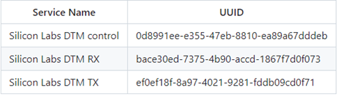
Once connected to Lyra dtm_test you can see the GATT Services; DTM Control, DTM RX and DTM TX. Note the services will not be presented as shown below. You will need to determine each service based on UUID which is shown on Bluetooth Wireless DTM but also provided below for demonstration.
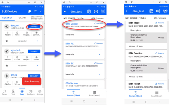
Expanding on the DTM Control Service the characteristics for that service can be observed. Each characteristic is written to configure the test as detailed at in Bluetooth Wireless DTM.
Further command and command argument information can be found on the Testing Commands page.
I’m interested in the source code of the Lyra AT Interface application and Wireless Xpress software solution. Where can I find, download, review and modify it?
Many thanks for your interest in our products. The Ezurio AT Interface implementation for both Lyra (22) and 24 series is closed source and proprietary, hence, we do not share any source code. This also applies to Wireless Xpress which was developed and released by Silicon Labs.
There are currently no plans to make any source files available to the public nor to open source our software projects on GitHub. For more details or individual requests, please reach out to your local sales representative or FAE at Laird.
Is the Silicon Labs Wireless Xpress software solution also available for Lyra 24?
Unfortunately, no. You cannot run Wireless Xpress on Lyra 24. There is no software and hardware support for it, and as now (2024) we have no plans to port, develop and/or release a compatible version for this hardware platform.
In you are migrating from a BGX-based device such as the BGX13 or BGX220, please feel free to investigate and review our Lyra (22) Series under https://www.lairdconnect.com/lyra-series in case you would like to continue using Wireless Xpress in your current design – but with one of our BLE modules as an alternative.
Also, please be advised that the Wireless Xpress software solution from Silicon Labs is frozen at its current release and therefore will not receive any further development or bug fixing in the future.
Do I have to configure UART hardware flow control (RTS/CTS) on my Lyra development board first, or is it already enabled by default?
All Lyra development boards are by default in a floating state and use an "auto" configuration for the virtual COM Port (VCOM); therefore, it is highly recommended to do so whenever possible. In this case, please refer here for instructions and more details on how to set up UART hardware flow control (RTS/CTS) properly with your Lyra hardware for evaluation.
Can I enable or disable UART hardware flow control (RTS/CTS) on my Lyra development board?
Yes. It is possible to enable and disable UART hardware flow control on your Lyra development board through Simplicity Studio 5 by modifying the Virtual COM Port (VCOM) settings. This for example can be helpful in cases where you would like to perform reference tests with or without having UART hardware flow control in place.
In Simplicity Studio 5 go to the Launcher page in the Debug Adapters view and right click on your Ezurio | Lyra Development Kit (ID:XXXXXXXXX). Select Launch Console and open the Admin tab. Now type "serial vcom config handshake rtscts" to enable or "serial vcom config handshake disable" for disabling UART hardware flow control.
Please make sure to reset or power cycle your Lyra development board once the settings have been applied. The default settings can be restored with the "serial vcom config handshake auto" command at any time.
When working with AT Interface firmware, what is the correct syntax to use the AT+LSCN command when not wanting to use all the optional parameters?
As
per the AT Interface User Guide, the AT+LSCN
AT+LSCN
Therefore,
the correct syntax for AT+LSCN without using all optional parameters would be
to leave the unused parameters blank (not a "0", just blank) while still dividing
each of the optional parameters using commas. For example, if the only
parameter required is to configure it the scan type (last parameter) to enable
scanning for 1M and Coded PHY (256k) with extended advertisements you would use
the following syntax:
AT+LSCN ,,,7
Please see the AT Interface User Guide for the module you
are working with for more information.
Lyra
Series Modules – AT Interface User Guide
Can the Lyra 24 modules support Wirepas MESH?
Lyra 24 modules do support Wirepas 2.4GHz Mesh. Wirepas added support of the EFR32BG24 BLE MCU in v5.4.0 FW release:
Wirepas Mesh 2.4 GHz Firmware v5.4.0 for EFR32xG24 Release Notes: Wirepas Developer Portal
With the larger 256K RAM size on the EFR32BG24 BLE MCU used on Lyra 24, Wirepas Nodes can be configured for LE Mode and Low Latency Node (Sink/Router Modes).
For more details on Lyra P and Lyra S Wirepas solution refer to the following page:
Wirepas Partnership (lairdconnect.com)
For information related to the Wirepas Mesh 2.4GHz FW v5.3.0 refer to the following Release Notes:
Why does it take so long for my VSP to establish a connection with a mobile device?
When making a connection to a mobile device using Lyra VSP service there is a 15 second delay between the "Ring" indication and the "Connect" indication. This issue is not actually a firmware issue and more of a use case issue. In a scenario whereby two LYRAs are connecting the central LYRA will kickstart the process and once a BT connection is established a series of commands will be sent to the peripheral LYRA to ensure the VSP is ready. These things include writing the Modem in & out descriptors to ensure that the devices are in a good state to send data (set to '1') and also to enable notifications on the Modem out and TX characteristics so that the central can view the incoming data.
In the case where a different non-LYRA device is acting as a central for a VSP connection these extra commands are not automatically sent therefore it is the central devices responsibility to send these commands.
Writing to the Modem In characteristic is the write that specifically breaks the peripheral LYRA out of the delay state and to output the connect message. This does not necessarily mean that the VSP system is ready the other commands must also be sent for the system to work properly.
If the 15 second delay is not tolerable for an application, then simply writing any value to the MODEM_IN Characteristic will allow the connection handshake to proceed. For example, using nRF Connect to connect to the Lyra DVK running VSP and connected to a UwTerminalX terminal, a simple write of 0xFF results will then show connect.
How is a static passkey configured for use in AT Interface Application/Firmware?
Lyra modules must be preloaded with AT Interface firmware, while BL65x modules must be updated to the most current smartBASIC firmware version and programmed with the AT Interface smartBASIC sample application in order to use any AT Interface commands.
To configure a static passkey using AT Interface it is necessary to ensure that the I/O capability of the modules will result in Passkey Entry authentication (per the Bluetooth SIG's IO Capabilities mapping). The Lyra or BL65x module must be configured with the I/O Capability set to Keyboard Only (2) or Keyboard + Display (4), via S Register 107, using the command, ATS 107=x, where x=2 for Keyboard Only or x=4 for Keyboard + Display.
Then the "AT+PKEY " command can be used to issue a static passkey to the underlying stack for use during a pairing procedure in future connections. The passkey must be a 6-digit integer in the range of 000000 – 999999.
The pairing will still use LESC Diffie-Hellman based exchanges. If a randomly generated number is used for the passkey the static passkey will be used.
Note: Pairing using a pre-programmed passkey makes pairing vulnerable to MITM attacks.
For more information on AT Interface configurations please reference the AT Interface User Guide for the specified module series.
Is the command used to set a static passkey with AT Interface firmware, AT+PKEY, persistent through a reset or power-cycle?
The AT+PKEY nnnnnn command, used by AT Interface to configure a static passkey, is an on-the-fly command and will not be persistent through a power-cycle/reset. Only S Register settings, using the ATS & AT%S commands, can be saved using AT&W followed by ATZ. All other AT commands are on-the-fly.
NOTE: Using a static, pre-programmed, passkey makes pairing vulnerable to MITM attacks.
For additional information on configuring a static passkey with AT Interface please refer to the appropriate AT Interface User Guide for the Ezurio module you are working with linked below:
User Guide - AT Interface Application - Lyra Series
Using STTY with the USB-SWD
These instructions are intended for Linux or Macintosh OS. They may work using WSL, Cigwin, or other bash style terminals in Windows although this is untested.
It may be desired to communicate with a device attached to the USB-SWD without terminal emulation, I.E. Picocom, Screen, Putty. This can be useful for writing bash scripts, or if you're using Zephyr's "west flash" and would like a quick way to check your output.
- Verify you have the program "stty" available using the command "which stty", if this does not return a value you will need to install it. Fortunately "stty" generally comes standard with Linux and MacOS.
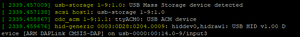
- Identify your serial device. This can be done using the command "dmesg -w" then connecting the USB-SWD. You will see output like this (In Linux).
- (Optional) Assign the device name to a variable, for example "DEVICE=/dev/ttyACM0".
- Configure "stty" to talk with the device "stty -F $DEVICE 115200 -echo -echoe -echok"
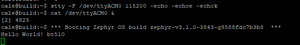
- To see output from the device execute "cat $DEVICE &". This will send serial communication from the device to Linux's standard output. The "&" is to run this program in the background.
- Now press the reset button on the USB-SWD, you should see the output from your device. In this example the Zephyr "Hello World" example has been flashed to a BT510.
- (Optional) if you would like to send commands back to the device you can use "echo" or add an argument to your shell, "foo() { echo -n -e "$1\r" > $DEVICE; }". Now commands can be issued directly from the command line, for example "foo "my_command"" will send the string "my_command" to the device.
Do I need UART hardware flow control (RTS/CTS) with Lyra, and what is your recommendation?
No, it is optional. However, Laird strongly recommends that developers make use of UART hardware flow control by implementing and connecting both RTS (Request to Send) and CTS (Clear to Send) lines in their Lyra designs – beside the regular RX (Receive) and TX (Transmit) pins.
Hardware flow control (also known as RTS/CTS flow control) is called so because the control is handled by the hardware. It is useful in scenarios where the transmitter is able to send data faster than the receiver is able to process. The RTS and CTS lines are turned off and on from alternate ends to control data flow, for instance when a buffer is almost full. This design approach is an effective way to prevent data loss and helps to guarantee data integrity in your application.
Which Silicon Labs Bluetooth Stack and Gecko SDK (GSDK) version is the Lyra AT Interface application / implementation based on?
Our AT Interface application and implementation for both Lyra (22) + 24 series are making use of the Silicon Labs Stack. They are based on the following − different − Bluetooth Gecko SDK (GSDK) versions:
- Lyra (22) series with Ezurio's GA release >= 2.2 (https://github.com/LairdCP/Lyra_Firmware/releases) is based on the Silicon Labs GSDK v4.0.2 (https://www.silabs.com/documents/public/release-notes/gecko-platform-release-notes-4.0.2.0.pdf)
- Lyra 24 series with Ezurio's GA release >= 1.1 (https://github.com/LairdCP/Lyra_24_Firmware/releases) is based on the Silicon Labs GSDK v4.2.0 (https://www.silabs.com/documents/public/release-notes/gecko-platform-release-notes-4.2.0.0.pdf)
Please also refer to https://www.silabs.com/developers/gecko-software-development-kit for additional information.
Resource Center
-
/filters:background_color(white)/2022-07/LYRA-P%20and%20LYRA-S%20render.380.png)
Ezurio Provides the Replacement for Now-EOL Silicon Labs BGX220 Modules
BGX220 Modules enter a Six-Month Last Time Buy Window The BGX220 Wireless Xpress Modules from Silicon Labs, based on the EFR32BG22 SoC, are EOL with a last time buy date of March 6,...
-
/filters:background_color(white)/2022-02/LYRA-P%20and%20LYRA-S%20render.380.png)
Coming Soon: Advanced Bluetooth LE Module Series in Partnership with Silicon Labs
The Lyra Series of Bluetooth LE modules based on Silicon Labs SoC is a major addition to our industry-leading portfolio of Bluetooth solutions. We are excited to announce that we have partnered with...
-
/filters:background_color(white)/2024-03/Lyra%2024%20-%20Collection1.png)
Future Proof Your Next Generation Bluetooth LE design – Capable, Flexible and Secure - The Lyra 24
An informative webinar on the Lyra 24 family utilizing Silicon Labs EFR32BG24 SoC, designed to empower your next generation Bluetooth Low Energy (LE) projects.
-
Laird Connectivity Extends Global Partnership with Silicon Labs Announcing the Lyra 24 Series
Next Generation Bluetooth LE for Advanced IoT Device Development
-
Laird Connectivity, in Partnership with Silicon Labs, Launches Advanced Bluetooth LE Module Series that Accelerates IoT Development
New Lyra Series of Bluetooth LE Modules Based on Silicon Labs SoC Is Major Addition to Laird Connectivity’s Industry-Leading Portfolio of Bluetooth Solutions Akron, Ohio – 15 February 2022 –...
-
/filters:background_color(white)/2024-02/Lyra24%20-%20Canvas.png)
New to our Canvas Software Suite: The Lyra 24 Series!
Our Canvas Software Suite provides tools, templates, sample applications, and more for Canvas-enabled hardware offerings in our portfolio. The Lyra 24 Series is our latest offering.
-
Now Available: Advanced Bluetooth LE Module Series in Partnership with Silicon Labs
The Lyra P is now in stock! The Lyra Series of Bluetooth LE Modules, based on Silicon Labs SoC, is a major addition to our industry-leading portfolio of Bluetooth solutions. The Lyra Series of...
-
Now Available: Lyra 24 USB
A next-generation Bluetooth LE USB adapter for advanced IoT device development.
-
/filters:background_color(white)/2023-08/453-00148-K1-Right%20Vertical.png)
Now Available: Lyra 24P Bluetooth 5.3 Solution
A next-generation Bluetooth LE module for advanced IoT device development.
-
/filters:background_color(white)/2023-04/Lyra%2024S%20SIP%20Dev%20Board.12.png)
Now Available: Lyra 24S Bluetooth 5.3 Solution
A next-generation Bluetooth LE module for advanced IoT device development.
-
Now in Stock: Advanced Bluetooth LE Module Series in Partnership with Silicon Labs
The Lyra S is now available! The Lyra Series of Bluetooth Low Energy (LE) modules, based on Silicon Labs SoC, is a major addition to our industry-leading portfolio of Bluetooth solutions. The...
-
/filters:background_color(white)/2023-07/Lyra24-Silicon-Labs-Partnership.png)
Our Lyra24 Partnership with Silicon Labs
Discussing the value we add to Silicon Labs' hardware in our Lyra24 Bluetooth modules.
Become an Ezurio Customer to Gain Exclusive Access to Our Design Experts
- Antenna Scans
- Antenna selection and placement
- Custom antenna design
- Worldwide EMC testing / certifications
- Embedded RF hardware / firmware design
- Cloud architecture and integration
- Mobile application development
- Product & Industrial Design
Buy Now
| Distributor | Part | In Stock | Region | Buy |
|---|---|---|---|---|
| Mouser | 450-00184 | 69 | North America | Buy Now |
| Mouser | 453-00142-K1 | 17 | North America | Buy Now |
| Mouser | 453-00142C | 240 | North America | Buy Now |
| Mouser | 453-00142R | 970 | North America | Buy Now |
| Mouser | 453-00145-K1 | 47 | North America | Buy Now |
| Mouser | 453-00145C | 228 | North America | Buy Now |
| Mouser | 453-00145R | 968 | North America | Buy Now |
| Mouser | 453-00148-K1 | 36 | North America | Buy Now |
| Mouser | 453-00148C | 360 | North America | Buy Now |
| Mouser | 453-00148R | 950 | North America | Buy Now |
| Mouser | 453-00170-K1 | 14 | North America | Buy Now |
| Mouser | 453-00170C | 624 | North America | Buy Now |
| Mouser | 453-00170R | 2500 | North America | Buy Now |
Distributors
| Distributor | Phone Number | Region | Website |
|---|---|---|---|
| Arrow Electronics | 1-855-326-4757 +44 2039 365486 |
APAC, North America, South America, EMEA | Website |
| Avnet | 1-480-643-2000 +44 1628 512900 |
APAC, North America, South America, EMEA | Website |
| Braemac Australia, New Zealand, South East Asia | +61 2 9550 6600 +64 9 477 2148 |
APAC | Website |
| Cal-Chip Connect | 1-215-942-8900 |
North America | Website |
| DigiKey | 1-800-344-4539 |
North America, South America, APAC, EMEA | Website |
| EBV Elektronik | EMEA | Website | |
| Farlink Technology China, Hong Kong | +86 13266922199 |
APAC | Website |
| Farnell | 1-800-936-198 +44 3447 11 11 22 |
EMEA | Website |
| Future Electronics | 1-800-675-1619 1-514-428-8470 |
North America, South America, APAC, EMEA | Website |
| Glyn | +49-6126-590-0 |
EMEA | Website |
| Hy-Line Germany Only | +49 89 614 503 0 |
EMEA | Website |
| Jetronic China, Hong Kong and Taiwan | 852-27636806 |
APAC | Website |
| Laird Connectivity | 1-847-839-6925 +44 1628 858941 |
North America, South America, APAC, EMEA | Website |
| M2M Germany | +49-6081-587386-0 |
EMEA | Website |
| Martinsson | +46 8 7440300 |
EMEA | Website |
| McCoy South East Asia | +65 6515 2988 |
APAC | Website |
| Mouser | 1-800-346-6873 +44 1494 427500 |
North America, South America, APAC, EMEA | Website |
| RS Components | +852-2421-9898 +44 3457-201201 |
North America, South America, APAC, EMEA | Website |
| Ryoyo Japan | +81-3-3543-7711 |
APAC | Website |
| Solsta UK Only | +44 (0) 1527 830800 |
EMEA | Website |
| Supreme Components International India, South East Asia | +65 6848-1178 |
APAC | Website |
| Symmetry Electronics | 1-866-506-8829 |
North America | Website |
| Tekdis Australia and New Zealand | +61 3 8669 1210 |
APAC | Website |
| Telsys | +972 3 7657666 |
EMEA | Website |
| WPG | +44 1628 958460 |
EMEA | Website |