Major Considerations for Integrating a Wireless Module
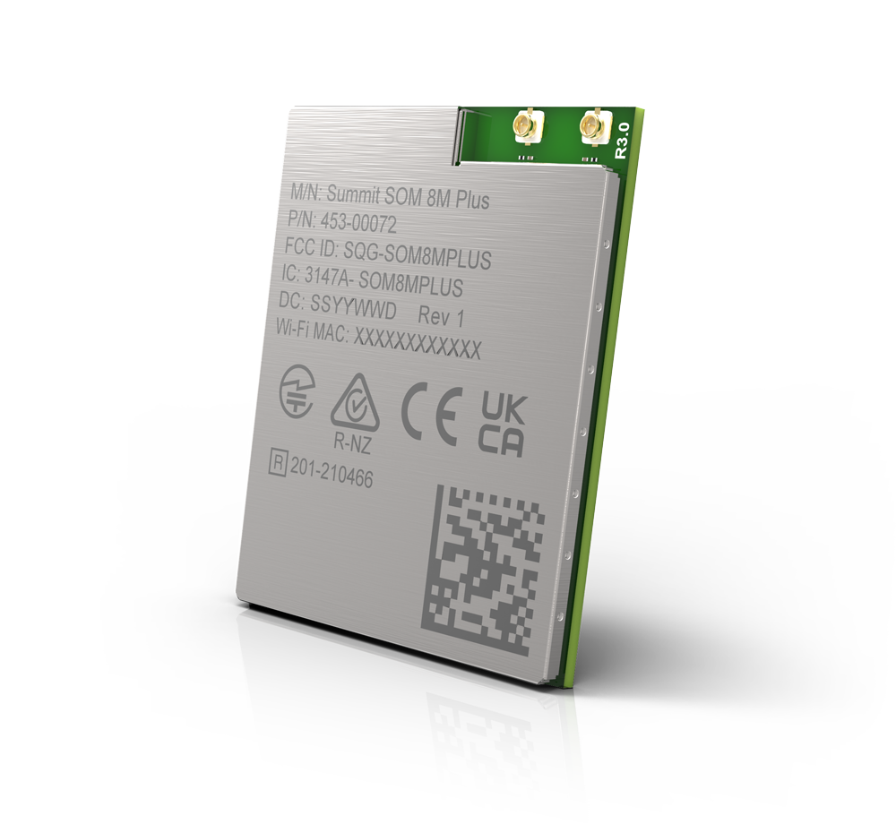
For all the things that OEMs can leverage in a wireless module, there are still a few remaining considerations. They are primarily in the following three categories: choice and placement of antenna, overall host board design, and RF trace consistency for compliance. Everything within the module itself is pre-engineered and laid out to prevent the OEM having to consider the inner workings of the wireless component itself. But it’s a bit like placing an engine in a car: the engine, to itself, is all ready to work as ordered. But it must be placed correctly. It has to fit in place. It has to be kept free of other parts getting in its way. The engine is designed with some expectations in place for it to work properly, and those expectations have to either be met or accounted for.
In this way, like nearly anything else in product design, the advantages of choosing a module come with some strings attached, some expectations from the module manufacturer that must be met in order for the overall design to work out. The following are examples of those considerations.
- Antenna choice and placement: Many of our wireless modules include an option with an included chip antenna pre-integrated into the module’s PCB. As long as module placement guidelines are followed, this provides a known working antenna configuration. But if the OEM chooses an external antenna, the antenna’s ground plane must be considered. The ground plane has to be the right size and in an RF-safe place. Ezurio pre-certifies antennas for our modules and provides guidance on integration, critical for compliance and performance.
- Host board design: RF design often displays unusual, borderline-mysterious behavior, and the shape of the OEM’s host board can create unexpected results. Large holes or cut-outs in the main board can warp and distort radiation patterns. Placement of the module or antenna near these can be especially destructive. And other components which might interfere have to be kept a safe distance away. Our white paper covers these in greater detail.
- RF Trace Design and EMC Compliance: In particular, leveraging any module provider’s certifications requires a careful adherence to the conditions of the original approval. That means following things like the maximum antenna gain from that approval or the safe distance from the human body for operation. In the FCC region, a particular RF trace pattern is required to leverage the approval, and any changes to that pattern will require retesting.
Following the Suggestions for Success
Ezurio knows that even the simpler path of using a wireless module still has its challenges, which is why we thoroughly document our modules’ hardware and software. Our module datasheets provide a wealth of information on our modules and their power requirements, pinouts, and suggestions for successful integration.
Additionally, our development boards provide a well-considered reference design for integrating our modules into another PCB. They are well-documented and demonstrate how to integrate additional connections, different power supply options, signaling levels of peripheral interfaces, and proper grounding.
Ezurio provides hardware, software, documentation, technical drawings, and thorough integration information to bring our expertise to our customers’ designs. And when problems arise, our best-in-industry global support and FAE teams are ready to help at every step. We’re a trusted partner with experience at every step of the design and manufacture process.
 Laird Connectivity is now Ezurio