 Laird Connectivity is now Ezurio
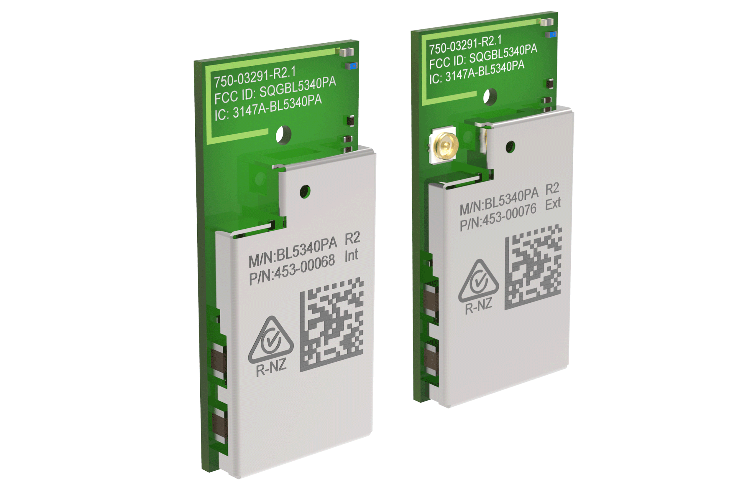
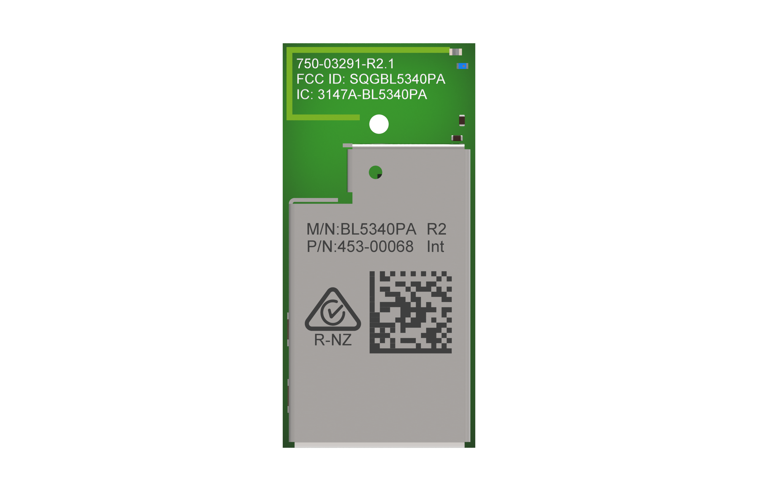
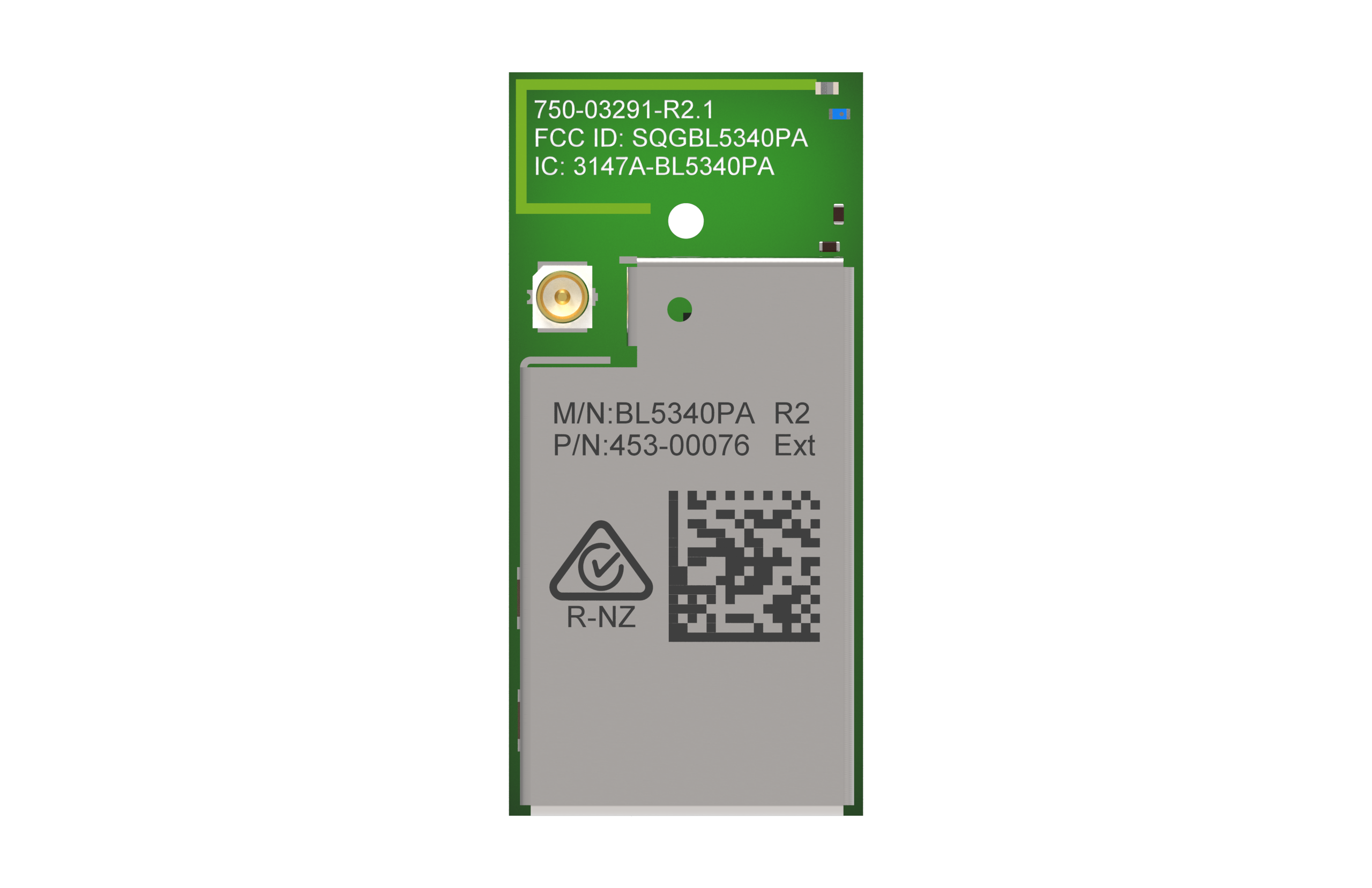
BL5340PA Series Long Range Bluetooth Module
Overview
Ezurio's (formerly Laird Connectivity) latest edition to their Nordic Semiconductor based Bluetooth LE portfolio, is the most advanced, secure, and highest performing dual core MCU architecture wireless solution available.
Based on the Nordic nRF5340 system-on-chip (SoC) and nRF21540 Front End Module (FEM), the BL5340PA series directly targets OEM customers requiring the longest range and highest MCU performance for their products’ wireless connectivity needs. Adding the nRF21540 RF FEM improves the link budget and connection robustness and significantly increases wireless range versus only using the nRF5340 SoC. The partnering of the nRF5340 and nRF21540 together into a certified module enables a wide range of use cases including industrial predictive maintenance and long range LE Audio capabilities.
The dual core Arm® Cortex M33 microcontrollers enable you to run a low power core focused purely on wireless connectivity, with a second higher performance core targeted for the end application itself. This further extends the multi-protocol capabilities of the product: Bluetooth LE, 802.15.4 (Thread/Zigbee) and NFC. It’s further enhanced with an ARM CryptoCell-312 including trusted execution, root-of-trust, and secure key storage security features.
The BL5340PA series brings out the nRF5340 & nRF21540 hardware features and capabilities including USB access, up to +18.5 dBm transmit power and a true industrial operating range of -40 to 105°C. Multiple regulatory certifications for both Bluetooth and 802.15.4 enables faster time to market and reduced development risk completes Ezurio's simplification of your next multi-protocol wireless design!
New Webinar:
BL5340PA - An easy-to-use module combining the power of the nRF5340 SoC with the range of the nRF21540 RF FEM
Watch our partner webinar with Nordic Semiconductor, where we give an introduction to the BL5340PA module, which seamlessly integrates the advanced nRF5340 SoC with the nRF21540 RF front-end module (FEM). Adding the nRF21540 RF FEM improves the link budget, connection robustness and significantly increases wireless range versus just using the nRF5340 SoC. These improvements are useful in various use cases, e.g, industrial and smart homes. All of this is in a small and certified module range with various integrated and external antenna options.
Specifications
802.15.4 (Thread/Zigbee)
NFC
MHF4 Connector
Nordic nRF Connect SDK
| Part Number | Antenna Type | Chipset (Wireless) | Frequency | Interfaces - General | Packaging | Product Type | Software | System Architecture | Technology |
|---|---|---|---|---|---|---|---|---|---|
| Integrated Antenna | Nordic nRF5340 | 2.4 GHz | USB, UART, QSPI, SPI, I2S, I2C, PDM, PWM, ADC, GPIO, QDEC, Comparator, Low Power Comparator | Tape/Reel | Embedded Module | Zephyr RTOS, Nordic nRF Connect SDK | Hostless | Bluetooth 5.2 |
 | MHF4 connector | Nordic nRF5340 | 2.4 GHz | USB, UART, QSPI, SPI, I2S, I2C, PDM, PWM, ADC, GPIO, QDEC, Comparator, Low Power Comparator | Tape/Reel | Embedded Module | Zephyr RTOS, Nordic nRF Connect SDK | Hostless | Bluetooth 5.2 |
| Integrated Antenna | Nordic nRF5340 | 2.4 GHz | USB, UART, QSPI, SPI, I2S, I2C, PDM, PWM, ADC, GPIO, QDEC, Comparator, Low Power Comparator | Cut Tape | Embedded Module | Zephyr RTOS, Nordic nRF Connect SDK | Hostless | Bluetooth 5.2 |
| MHF4 connector | Nordic nRF5340 | 2.4 GHz | USB, UART, QSPI, SPI, I2S, I2C, PDM, PWM, ADC, GPIO, QDEC, Comparator, Low Power Comparator | Cut Tape | Embedded Module | Zephyr RTOS, Nordic nRF Connect SDK | Hostless | Bluetooth 5.2 |
Development Kits
/filters:background_color(white)/2023-02/453-00068-K1.png)
/filters:background_color(white)/2023-02/453-00076-K1.png)
Documentation
Can I use your FEM driver for BL5340PA to change gain value on the nrf21540?
We don't currently support changing the gain of the FEM to lower power with an API. This is not supported in the Nordic driver. The FEM has two calibrated gain settings - one that achieves 20 dBm output and one that achieves 10 dBm output (both with 0 dBm input). However, you can change the output power level as discussed in the following FAQ.
Can I lower the TX Power on the BL5340 from the maximum set by the FW? (lairdconnect.com)
Can I lower the TX Power on the BL5340 from the maximum set by the FW?
The power level can lowered at compile time by changing
CONFIG_BT_CTLR_TX_PWR_ANTENNA from 20 to x. Power is split into two pieces
(nrf53 + FEM). Most of the granularity in power steps of the nRF53 is
used obtain the output required for RF compliance. Therefore, the granularity
of any further reductions in output power is limited.
For example, for TX Power = 12, this value is specified via
CONFIG_BT_CTLR_TX_PWR_ANTENNA and the driver will try to get as close as it
can.
The nRF5340 SoC output power has granularity of 0, -1, -2,
-3, -4, -5, -6, -7, -8, -12, -16, -20, -40. However, 0 to -8 may already be
used to achieve compliance for 20 dBm output at the antenna.
How can I get the maximum transmit (TX) gain for a specific region using the BL5340PA?
You will need to specify the antenna type and region in your board file or project
configuration file. Based on those parameters, the FW will set the maximum allowable TX power for each channel and modulation.
The default for the BL5340PA DVK is North America (FCC/IC),
using an external antenna.
Refer to the BL5340PA_manifest link below for
details:
Does the BL5340, BL5340PA, BL65x and Lyra BLE modules include the DC-DC LC filters on the module?
Yes, all BT modules
include the needed LC filter components required for DC-DC Converter operation.
Lyra P and Lyra S modules include a 2.2uH inductor on VREGSW output and 4.7uF capacitor to ground.
The nRF528xx used on the BL65x modules use two voltage regulators, REG0 and REG1. In Normal Voltage mode only REG1 is enabled. In High Voltage mode both REG1 and REG0 are enabled. The BL65x modules include 10uH and 15nH inductors on DCC output and 1.0uF capacitor to ground on REG1. REG0 includes a 10uH inductor on DCCH output and 4.7uF cap to ground.
Note: The BL651 module uses the nRF52810
which uses a single voltage regulator. The BL651 includes 10uH and 15nH
inductors on DCC output and 1.0uF capacitor to ground.
The nRF5340 used on the BL5340 and BL5340PA modules uses four voltage regulators, Main Voltage Regulator, Radio Voltage Regulator, High Voltage Regulator and a USB Regulator. In Normal Voltage mode the Main Voltage and Radio regulators are enabled while the High Voltage Regulator is disabled. In High Voltage mode the High Voltage regulator is enabled along with the Main Voltage and Radio regulators. The BL5340 module includes a 10uH inductor on the DCC outputs and 1uF capacitor to ground on the Main Voltage and Radio Voltage regulators. The High Voltage regulator includes a 10uH inductor on the DCCH output and 2.2uF capacitor to ground. The USB regulator uses an LDO only an no DC-DC filter components are needed.
What firmware do the BL5340/BL5340PA modules ship with initially? Can they initially be programmed via UART or FOTA or is it necessary to implement the SWD Interface?
As per section 3.7 of the BL5340/BL5340PA datasheets (links provided below) , these modules ship with no firmware loaded. Therefore, there is no Bootloader loaded to enable loading applications via UART and no support for FOTA (Firmware Over-the-Air) updates. It will be necessary to bring out the SWD interface on the PCB to enable programming the module with Nordic's nRF Connect SDK which uses the Zephyr RTOS platform. Once the Bootloader and/or FOTA firmware have been loaded to the module it should be possible to load future firmware updates via the UART or FOTA methods. See the Nordic DevZone for additional information on Bootloader and FOTA firmware options.
Datasheet - BL5340 Series
Datasheet - BL5340PA Series
Does the BL654PA or BL5340PA have EU Regulatory certifications (CE/EN)?
The BL654PA module has not been certified in EU as
regulatory restrictions limit TX Power spectral density to +10dBm/1 MHz. The
same requirements are true for the BL5340PA, but this module will achieve regulatory approvals in the EU with TX Power set below +10dBm.
Operating a radio device in the 2.4GHz frequency band there
apply certain regulatory requirements with regards to the maximum usable TX
output power. It ultimately comes down to the RF power spectral density instead
of a flat maximum TX power value.
ETSI EN 300 328 technically allows for 20dBm RF output power
for equipment when Adaptive Frequency Hopping (AFH) and at least 15 channels
are available. The only limitation is maximum 20 dBm for equipment meeting
these requirements. However, the Nordic SoftDevice or nRF Connect SDK
SoftDevice Controller does not provide a means for AFH. In this case the Power
Spectral Density must be tested which limits the maximum radiated power to
10dBm/MHz.
While technically it would be possible to offer a module in
the EU that can operate >10dBm, there are many hurdles in implementation
that would increase development effort and cost.
How can I change the 32.768KHz Low Power Clock Source using nRF Connect SDK v2.x?
With nRF Connect SDK v2.0.0 and later only VS Code is made
available as an IDE as VS Code provides many features including both Command
Line Interface (CLI) and Graphical User Interface (GUI) in one environment.
Prior to nRF Connect SDK, the 32.768KHz source in nRF5 SDK applications defaulted to using the external crystal oscillator. The BL65x DVK’s populate an external 32.768KHz crystal but it is not connected via open solder bridges. Therefore, either the solder bridges need to be shorted to make the external crystal connection or change the clock source to internal RC Oscillator via the sdk_config.h file.
With nRF Connect SDK the correct 32KHz clock source is selected depending on the EVK. For BL654 DVK examples are built using internal RC oscillator. On BL5340 DVK the external crystal oscillator is selected as the DVK does close the solder bridge pads.
If the 32KHz clock source needs to be changed an application can change accordingly in the prj.conf file of the project. The following direct dependencies need to be added to prj.conf to override the default clock configuration.
External Crystal Oscillator and accuracy selection:
CONFIG_CLOCK_CONTROL_NRF_K32SRC_50PPM=y
Internal RC Oscillator and accuracy selection:
CONFIG_CLOCK_CONTROL_NRF_K32SRC_RC=y
CONFIG_CLOCK_CONTROL_NRF_K32SRC_500PPM=y
Kconfig dependencies can be found:
https://developer.nordicsemi.com/nRF_Connect_SDK/doc/2.3.0/kconfig/index.html
Using STTY with the USB-SWD
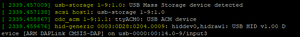
These instructions are intended for Linux or Macintosh OS. They may work using WSL, Cigwin, or other bash style terminals in Windows although this is untested.
It may be desired to communicate with a device attached to the USB-SWD without terminal emulation, I.E. Picocom, Screen, Putty. This can be useful for writing bash scripts, or if you're using Zephyr's "west flash" and would like a quick way to check your output.
- Verify you have the program "stty" available using the command "which stty", if this does not return a value you will need to install it. Fortunately "stty" generally comes standard with Linux and MacOS.
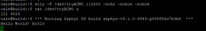
- Identify your serial device. This can be done using the command "dmesg -w" then connecting the USB-SWD. You will see output like this (In Linux).
- (Optional) Assign the device name to a variable, for example "DEVICE=/dev/ttyACM0".
- Configure "stty" to talk with the device "stty -F $DEVICE 115200 -echo -echoe -echok"
- To see output from the device execute "cat $DEVICE &". This will send serial communication from the device to Linux's standard output. The "&" is to run this program in the background.
- Now press the reset button on the USB-SWD, you should see the output from your device. In this example the Zephyr "Hello World" example has been flashed to a BT510.
- (Optional) if you would like to send commands back to the device you can use "echo" or add an argument to your shell, "foo() { echo -n -e "$1\r" > $DEVICE; }". Now commands can be issued directly from the command line, for example "foo "my_command"" will send the string "my_command" to the device.
Do the NFC traces need to be controlled differential impedance between NFC1 and NFC2?
The NFC track does not need to be routed with a controlled differential impedance. The NFC antenna is different from the BLE antenna as it's differential and not 50 Ohm (each track is 50 Ohm single ended). Also, the frequency is very low, so the exact impedance doesn't matter as much. The inductance in the antenna is what matters for the NFC antenna. Since the antenna is differential, it's better to use a two-pin connection instead of U.FL which is a single ended connection.
The inductance of the antenna together with the NFC antenna tuning capacitors forms a resonant circuit that is tuned to the NFC frequency, 13.56 MHz. Any change in the connection wires to the antenna can be compensated with the tuning caps.
How many LE Audio channels could be transferred on the BL5340 module at the same time?
For VQ (voice quality) at 8-bit 24kbps with 3 retransmissions. 4 is possible. Limiting factor is CPU processing of LC3 encode. OTA (over-the-air) bandwidth has room for more channels if you consider an additional CPU for LC3 processing.
Note Ezurio maintains a partnership with Packetcraft for LE Audio SW Solution.
Can more BL5340 modules work in parallel for channel expansion?
Yes, every module can handle 4 channels. Additional modules may be used for additional channels. But there are RF interference concerns with the higher number of transmitters from additional modules. Possible to coordinate the modules so they do not interfere but may need to consider something more sophisticated to coordinate the devices to maximize the 2.4GHz spectrum.
Note Ezurio maintains a partnership with Packetcraft for LE Audio SW Solution.
https://www.packetcraft.com/
Is it safe to run a Ezurio Bluetooth module through a PCBA wash cycle?
In general, cleaning the populated modules is strongly discouraged. Residuals under the module cannot be easily removed with any cleaning process.
- Cleaning with water can lead to capillary effects where water is absorbed into the gap between the host board and the module. The combination of soldering flux residuals and encapsulated water could lead to short circuits between neighboring pads. Water could also damage any stickers or labels.
- Cleaning with alcohol or a similar organic solvent will likely flood soldering flux residuals into the RF shield, which is not accessible for post-washing inspection. The solvent could also damage any stickers or labels.
- Ultrasonic cleaning could damage the module permanently.
However, if water washing is required you will need to use deionized water. We do not recommend chemical cleaning and cannot guarantee it will not damage the modules. If you MUST clean PCB with chemicals it is recommended that you test on one board and then confirm the module still works after the process, prior to adding it to production, while understanding the above affects washing the populated PCBs can have on the module.
Become an Ezurio Customer to Gain Exclusive Access to Our Design Experts
- Antenna Scans
- Antenna selection and placement
- Custom antenna design
- Worldwide EMC testing / certifications
- Embedded RF hardware / firmware design
- Cloud architecture and integration
- Mobile application development
- Product & Industrial Design
Buy Now
| Distributor | Part | In Stock | Region | Buy |
|---|---|---|---|---|
| Mouser | 453-00068-K1 | 19 | North America | Buy Now |
| Mouser | 453-00068C | 204 | North America | Buy Now |
| Mouser | 453-00068R | 983 | North America | Buy Now |
| Mouser | 453-00076-K1 | 20 | North America | Buy Now |
| Mouser | 453-00076C | 222 | North America | Buy Now |
| Mouser | 453-00076R | 972 | North America | Buy Now |
Distributors
| Distributor | Phone Number | Region | Website |
|---|---|---|---|
| Arrow Electronics | 1-855-326-4757 +44 2039 365486 |
APAC, North America, South America, EMEA | Website |
| Avnet | 1-480-643-2000 +44 1628 512900 |
APAC, North America, South America, EMEA | Website |
| Braemac Australia, New Zealand, South East Asia | +61 2 9550 6600 +64 9 477 2148 |
APAC | Website |
| Cal-Chip Connect | 1-215-942-8900 |
North America | Website |
| DigiKey | 1-800-344-4539 |
North America, South America, APAC, EMEA | Website |
| EBV Elektronik | EMEA | Website | |
| Farlink Technology China, Hong Kong | +86 13266922199 |
APAC | Website |
| Farnell | 1-800-936-198 +44 3447 11 11 22 |
EMEA | Website |
| Future Electronics | 1-800-675-1619 1-514-428-8470 |
North America, South America, APAC, EMEA | Website |
| Glyn | +49-6126-590-0 |
EMEA | Website |
| Hy-Line Germany Only | +49 89 614 503 0 |
EMEA | Website |
| Jetronic China, Hong Kong and Taiwan | 852-27636806 |
APAC | Website |
| Laird Connectivity | 1-847-839-6925 +44 1628 858941 |
North America, South America, APAC, EMEA | Website |
| M2M Germany | +49-6081-587386-0 |
EMEA | Website |
| Martinsson | +46 8 7440300 |
EMEA | Website |
| McCoy South East Asia | +65 6515 2988 |
APAC | Website |
| Mouser | 1-800-346-6873 +44 1494 427500 |
North America, South America, APAC, EMEA | Website |
| RS Components | +852-2421-9898 +44 3457-201201 |
North America, South America, APAC, EMEA | Website |
| Ryoyo Japan | +81-3-3543-7711 |
APAC | Website |
| Solsta UK Only | +44 (0) 1527 830800 |
EMEA | Website |
| Supreme Components International India, South East Asia | +65 6848-1178 |
APAC | Website |
| Symmetry Electronics | 1-866-506-8829 |
North America | Website |
| Tekdis Australia and New Zealand | +61 3 8669 1210 |
APAC | Website |
| Telsys | +972 3 7657666 |
EMEA | Website |
| WPG | +44 1628 958460 |
EMEA | Website |